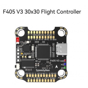
SpeedyBee F405 V3 30x30 Flight Controller
Product Name: SpeedyBee F405 V3 30x30 Flight Controller
MCU: STM32F405
IMU (Gyro): BMI270
USB Port Type: Type-C
Barometer: Built-in
OSD Chip: AT7456E chip
BLE Bluetooth:
Supported. Used to connect with the SpeedyBee App for flight controller and ESC parameter configuration. Ensure the MSP switch on UART 4 is turned on and set to a baud rate of 115200, otherwise, Bluetooth functionality will not be available.
WIFI: Not supported
DJI Air Unit Connection Way:
Two ways supported: 6-pin connector or direct soldering.
6-pin DJI Air Unit Plug:
Supported. Completely compatible with DJI O3/RunCam Link/Caddx Vista/DJI Air Unit V1, no wire changes needed.
Blackbox MicroSD Card Slot:
Betaflight firmware requires the microSD card type to be either Standard (SDSC) or High capacity (SDHC); extended capacity cards (SDXC) are not supported. Many high-speed U3 cards are SDXC. The card MUST be formatted with the FAT16 or FAT32 (recommended) filesystems. You can use any SD card less than 32GB, but Betaflight can only recognize 4GB maximum. We suggest using a third-party formatting tool and choosing 'Overwrite format' to format your card. Check for recommended SD cards or purchase tested cards from our store.
BetaFlight Camera Control Pad: Yes (CC pad on the front side)
Current Sensor Input:
Supported. For SpeedyBee BLS 50A ESC, set scale = 386 and Offset = 0.
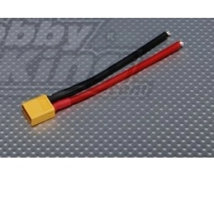
Power Input:
3-6S LiPo. The flight controller is powered through the G, V wires of the 8-pin cable or G, V pads from the bottom side of the flight controller.
5V Output:
9 groups of 5V output
Four +5V pads and 1 BZ+ pad (used for Buzzer) on the front side
4x LED 5V pads
Total current load: 2A
9V Output:
2 groups of 9V output
One +9V pad on the front side and another included in a connector on the bottom side
Total current load: 2A
3.3V Output:
Supported. Designed for 3.3V-input receivers. Up to 500mA current load.
4.5V Output:
Supported. Designed for receiver and GPS module even when the FC is powered through the USB port. Up to 1A current load.
ESC Signal:
M1 - M4 on the bottom side and M5-M8 on the front side.
UART:
6 sets: UART1, UART2, UART3, UART4 (Dedicated for Bluetooth connection), UART5 (Dedicated for ESC telemetry), UART6
ESC Telemetry: UART R5 (UART5)
I2C:
Supported. SDA & SCL pads on the front side. Used for magnetometer, sonar, etc.
Traditional Betaflight LED Pad:
Supported. 5V, G, and LED pads on the bottom of the front side. Used for WS2812 LED controlled by Betaflight firmware.
Buzzer:
BZ+ and BZ- pad used for 5V Buzzer
BOOT Button:
Supported.
Press and hold BOOT button and power the FC on simultaneously to force the FC into DFU mode for firmware flashing if the FC gets bricked.
When the FC is powered on and in standby mode, the BOOT button can control the LED strips connected to LED1-LED4 connectors on the bottom side. By default, short-press the BOOT button to cycle the LED display mode. Long-press the BOOT button to switch between SpeedyBee-LED mode and BF-LED mode. Under BF-LED mode, all the LED1-LED4 strips will be controlled by Betaflight firmware.
RSSI Input: Supported (Named as RS on the front side)
Smart Port / F.Port: Not supported
Supported Flight Controller Firmware:
BetaFlight (Default)
INAV (INAV firmware can only use Multishot (recommended) and OneShot125. DShot is not supported.)
Firmware Target Name: SPEEDYBEEF405V3
Mounting: 30.5 x 30.5mm (4mm hole diameter)
Dimensions: 41.6(L) x 39.4(W) x 7.8(H) mm
Weight: 9.6g
 Airsoftas, Šratasvydis
 Akumuliatoriai, pakrovėjai
 FPV Dronai
 Lėktuvai
 RC Automodeliai
 Priemonės konstravimui
 Valdymai ir imtuvai
 FPV Įranga
 Naudoti
 Laivai Tankai Sraigtasparniai
 3D Spausdinimas
 Airsoft EU Sandėlys
 Aitvarai
 Dovanų kuponai
 Kompiuterija
 Propeleris.lt sandėlis
 Servisas
 Žaislai