Turime vietoje, pristatymas kurjeriu/paštomatu sekančią darbo dieną.
15.99
€
Kaunas:
YRA
Vilnius:
NĖRA, galimas atsiėmimas sekančią darbo dieną
Užsakymai pateikti iki 17h išsiunčiami tą pačią darbo dieną, dažniausiai pristatomi sekančią darbo dieną.
Prekės informacija
Gaminio savybės
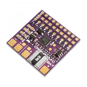
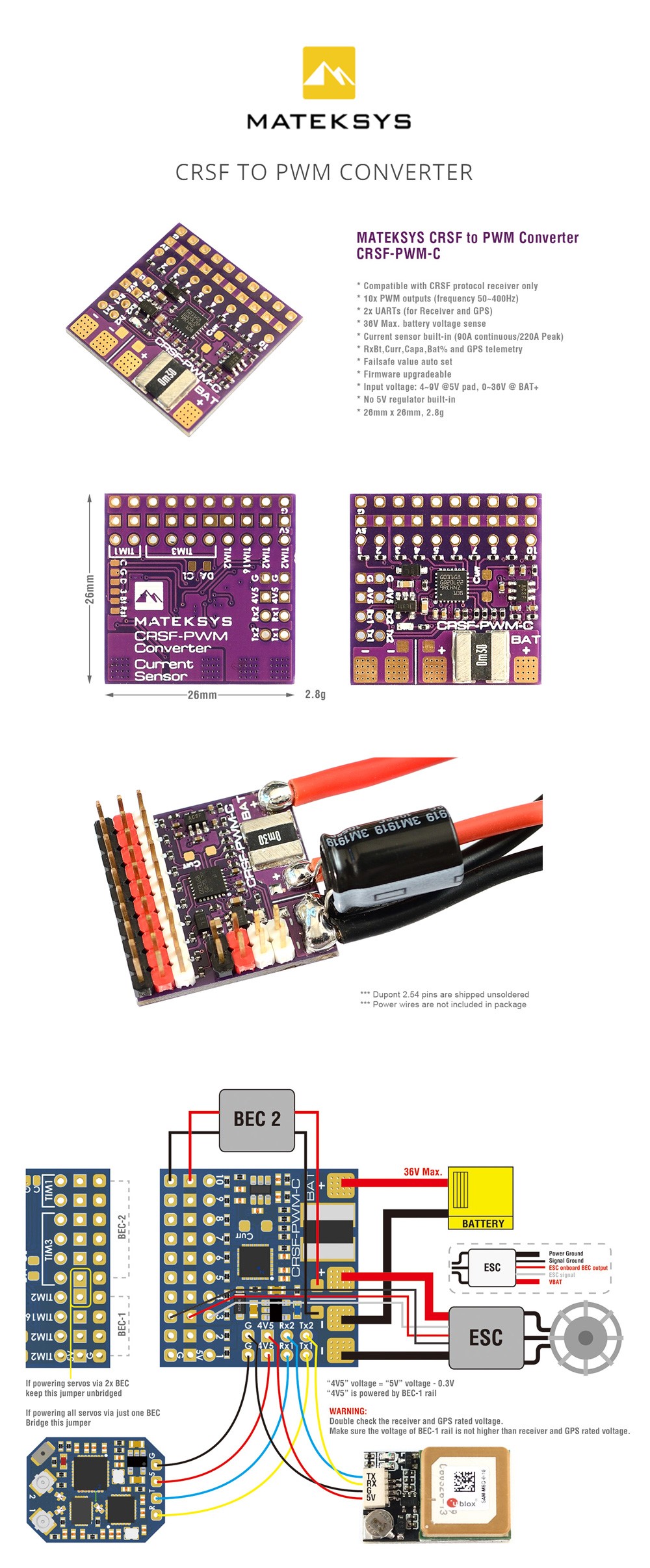
The MATEKSYS CRSF PWM C is a Crossfire to PWM Converter with 2 UARTS and 10 PWM Outputs. This converter supports any Crossfire Protocol receivers, such as the 433MHz, 868MHz, 915MHz, or 2.4GHz.
Features
Compatible with Crossfire Receivers Only No 5V Regulator Built-in Built-in Current Sensor Failsafe Value AutoSet Firmware Upgradeable 10 PWM Outputs 2 UARTS
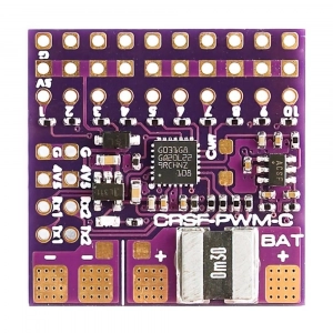
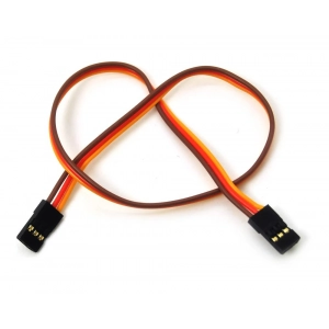
PINOUTS AND PADS
4v5 pad voltage = 5V pad voltage -0.3V, make sure the voltage on the 5V pad is not higher than receiver and GPS rated voltage. Tx2/Rx2(UART2) for GPS/firmware update/setting parameters Tx1/Rx1(UART1) for CRSF protocol Receiver Vbat: Battery voltage sensing (0~36V) Curr: current sensor signal (0~3.3V) 1~10: CH1~CH10 PWM outputs G: ground
FAILSAFE
Failsafe value is set automatically after the CRSF-PWM board is powered on and receives the CRSF signal. LED blinks 8 times quickly. Failsafe value = The PWM value of each channel(except CH3) when the CRSF signal is received by the CRSF-PWM board for the first time CH3 is specially arranged for the throttle, Failsafe value = 988 by default. Put the throttle joystick to the lowest point, put AIL(Roll), ELE(Pitch), RUD(Yaw) middle before powering on the receiver.
LED STATUS
Slow blinks: CRSF-PWM board doesnt receive a CRSF signal, e.g., the receiver is not bound with the transmitter, the receiver is not connected to UART1 of the CRSF-PWM board. 8x quick blinks: CRSF-PWM board received CRSF signal and failsafe value is saved. 2x slow blinks between 8x fast blink and solid on: CLI mode is active solid ON: CRSF-PWM board and receiver are working normally
GPS TELEMETRY
Troubleshooting for no GPS telemetry, double-check the wiring between GPS and CRSF-PWM board, some u-Blox GPS may dont output NMEA protocol, you need to be reverted GPS to the default configuration in u-center. Sensors(GPS, GSpd, Hdg, Alt, Sats) will blink in the Transmitter TELEMETRY tab once the CRSF-PWM board has a connection with GPS. GPS TX to CRSF-PWM board RX Single wire half-duplex UART connection, CRSF-PWM board TX to GPS RX is not essential. with OpenTX Telemetry Logging, You can plot your flight path or search the lost plane. u-Blox series GPS can output the 0+1 UBX+NMEA protocol by default Compatible with GPS NMEA protocol, 1Hz, Baud 9600~115200 Support GPS Telemetry ID: GPS, GSpd, Hdg, Alt, Sats
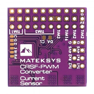
TIM & PWM FREQUENCY
PWM frequency on all 10x Channels can be configured according to TIM PWM runs at 50Hz by default TIM3: CH5, CH6, CH7, CH8 TIM2: CH1, CH2, CH4 TIM1: CH9, CH10 TIM16: CH3
CLI MODE
If the CRSF-PWM board doesnt detect GPS connected to UART2 within 10 seconds after powering on, CLI mode will active. After CLI mode is active, the CRSF-PWM board can be connected to the configurator via USB-TTL module/FC passthrough. CLI mode has no effect on receiver CRSF signal and PWM outputs In CLI mode, CRSF-PWM board firmware can be updated
Specifications
Support: Any CRSF protocol receivers (including 433MHz, 868MHz, 915MHz, 2.4GHz) Current sensor: Built-in (90A continuous /220A Peak), current scale = 150 by default Telemetry ID: RxBt, Curr, Capa, Bat%, GPS, GSpd, Hdg, Alt, Sats PWM frequency configurable (50Hz default, 100,160,330, 400Hz) 36V Max. battery voltage sense (1K:10K voltage divider built-in) Rated voltage: 4~9V @5V pad, 0~36V @BAT+ Vbat and Current sensor scale configurable UARTs (for Receiver and GPS): 2 Size: 26mm x 26mm PWM outputs: 10 Weight: 2.8g
 Airsoftas, Šratasvydis
 Akumuliatoriai, pakrovėjai
 FPV Dronai
 Lėktuvai
 RC Automodeliai
 Priemonės konstravimui
 Valdymai ir imtuvai
 FPV Įranga
 Naudoti
 Laivai Tankai Sraigtasparniai
 3D Spausdinimas
 Airsoft EU Sandėlys
 Aitvarai
 Dovanų kuponai
 Kompiuterija
 Propeleris.lt sandėlis
 Servisas
 Žaislai